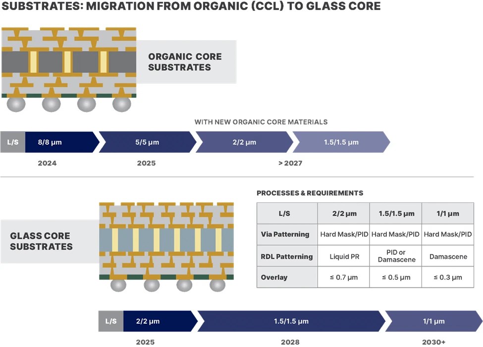
Advanced IC substrates (AICS) have been marching toward the 2µm line/space (L/S) redistribution layer (RDL) technology node for some time (figure 1). However, many questions remain about the ability of organic substrates to meet the line/space requirements of the next generation of advanced packages (AP), those below 2µm L/S and perhaps to 1.5µm L/S. Simply put: are organic substrates up to the challenge?

Fig. 1: The industry roadmap for the transition of substrates from organic (top) to glass (bottom) and the path to 1µm L/S. Source: Onto Innovation.
The answer to that has been no.
But with recent developments, the possibility of organic substrates reaching below 2µm appears to be changing.
Before we discuss the reasons why, we will first turn our attention to the core reasons organic substrates struggle with lower line/space requirements.
Distortion and defects
Organic substrates can suffer from deformation during the curing of dielectric build-up films. The result: distortion in the X/Y plane that impacts the topography of the substrate surface, hindering its use at finer nodes. In addition, the electroless copper seed metal used in the RDL plating process is, unfortunately, not suitable for fine linewidth interconnects, given the metal’s roughness and large grain boundaries.
Still, there’s hope for organic substrates to make it below 2µm L/S.
One such innovation to improve via placement accuracy could be to use photo imageable dielectric (PID) materials to replace laser drilled vias. An alternate innovation: manufacturers could use a resist-patterned hard mask to define the via dimensions and then dry etch the build-up film on the copper surface of the previously patterned RDL. Both of these innovations would provide significant lithography improvements to overlay and via resolution.
For the patterning of fine line interconnects, the use of liquid photoresist could also improve the resolution capability since dry film negative tone resist is limited to around 4:1 in the thinner films. This approach would also be useful for higher aspect ratio resist options.
Be that as it may, these efforts will only take organic substrates so far. Line/space requirements lower than 1.5µm will likely be out of reach.
And then there’s another obstacle: these innovations have no value unless defect density is low enough to support the large RDL areas of next-generation AP designs. As fine line interconnects shrink, so do the critical defect dimensions causing yield loss. Take this scenario for example: a 5µm L/S protrusion of 2µm is manageable, but at 2µm L/S the same defect would cause an interconnect to bridge and the failure of the package.
The primary cause of defects comes from organic residue leftover from RDL and PID processing. However, finding these defects is difficult with an automated optical inspection (AOI) system. The reason: the grain boundaries on top of the rough copper generate too much noise. Although solutions are available, they will reach their limits as defects shrink further.
In addition to residue, RDL bridging and opens are concerns. These will be even more difficult to detect and classify below 1µm L/S.
A clear future
Unlike organic substrates, the future is clear for glass substrates: they have the greatest potential to achieve the 1µm L/S technology node due to their stability and electrical properties. Furthermore, replacing plated through holes (PTHs) with through glass vias (TGVs) increases the density of front-to-back connections.
Of course, nothing is ever easy in the world of process control. TGVs pose challenges as well. The size (CD), roundness, X/Y location and sidewall profile are critical to package performance. Even more crucial, every single one of the millions of TGVs in the package must be inspected. After all, one missing TGV could cause a complete package failure.
While defect inspection is important, metrology analytics and data visualization should play a role in setting up a TGV process. Understanding the TGV critical dimension (CD) bias between the front and back of the substrate, side wall profile, CD uniformity and missing via signatures is key in determining the root cause of defects and maintaining high substrate yields. In addition, RDL and build-up film via formation processes will need to be modified like organic substrates to reach 1.5µm L/S. But even with these innovations, glass technology will struggle to achieve 1µm L/S, leading to a new round of innovation.
Until now, the process of defining the substrate RDL has been through the plating of interconnects. These interconnects are defined by a photoresist line/space pattern, or mold, where the plated copper metal fills the spaces in the photoresist mold. Once plated, the photoresist mold is stripped. After that, the copper seed is removed using a wet chemistry process called a flash etch, revealing final fine copper lines. The flash etch step removes both copper seed and the surface of the plated RDL structures. This reduces CD and height across the substrate surface.
To mitigate the effects of this step, the lithography reticle is typically biased such that the gap between the RDL lines is increased by two times the thickness of the copper seed. This impacts lithography resolution requirements since the larger gap between the lines shrinks the photoresist line width to maintain the same pitch. For example, a 2µm L/S copper interconnect, with a copper seed layer of 2,500Å, requires a resist linewidth of 1.5µm, with a space of 2.5µm. The final interconnect would be 2µm L/S once the seed metal is flash etched. This is caused by the isotropic nature of the wet etch. This method works well for large RDL dimensions but requires lithography systems capable of imaging smaller geometries to meet final L/S dimensions.
At 1.5µm L/S, this line/space bias will be difficult to control since the lithography resist line width will be only 1µm and the space will be 2µm. This will be complicated by the thick plating photoresist, which is typically greater than 6µm, requiring an aspect ratio of 6:1. This makes matters even more challenging.
The requirements for high aspect ratio photoresist imaging are likely to be beyond the capability of most dry film resists available today. At this technology node a change in photoresist chemistry — from dry film to liquid photoresist — will probably be required to realize the 6:1 aspect ratio. As a result of these photoresist limitations, new approaches will be needed to support AP roadmap milestones below 1.5µm L/S. One option could involve utilizing a damascene process, similar to the front-end, but using organic material (build-up film or PID) as the dielectric instead of inorganic SiO2/Si3N4 which is used in the front-end. A number of different approaches could be employed to develop a damascene process for advanced packaging.
We will continue this discussion in our next blog where we will dive further into the use of PID materials and hard masks to reach the ever-stringent line/space requirements for advanced IC substrates. Regardless of which techniques are ultimately employed, the road to and below 1.5µm L/S will bring many challenges, challenges that no single substrate type is immune from.

